

However long one considers it, one eventually stumbles against the problem of how to equip "normal" locos with TELEX. Many years ago a retro-'do-it-yourself' installation of TELEX was already described in the Märklin Magazine. This, however, concerned the re-building of a tender-hauled loco, by use of the relevant parts, into another TELEX-Loco -and thus unfortunately it did not cater for this problem.
 There was therefore no way around it, but to personally get to grips with the matter. With some 0-6-0 locos- particularly the well known "3000" - sufficient space is available to house the standard -TELEX - coupling, comprising the magnet, coupling hook, loop and the spring.
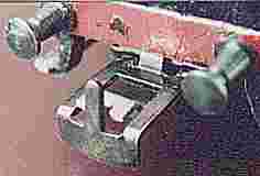
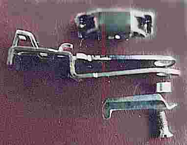
The adjacent illustration shows the necessary spare parts. Not visible is a loop through which the coupling hook is led, manufactured from a narrow strip of metal ; see heading illustration above. From top to bottom:
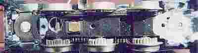 The essential and demanding work now arises, to create the space for the magnet in the Chassis - as well as, if necessary, the guide/gap for the coupling hook in the various imitation compressed-air cylinders . If one has a milling machine to hand, there is not much difficulty in milling the space for the magnets at front and rear. The adjacent picture shows the result of the milling work; on the left the TELEX - magnet is inserted already. Milling free-hand is, on the other hand, a rather laborious and lengthy venture, with no certainty of a satisfactory result.
Here one must mill as deeply as possible and necessary, since the core of the magnet may not project below the chassis. With some locos it can therefore be necessary to also remove some material from the stator. In order to avoid attraction of the anchor and unintentional un-coupling (due to magnetic generation) during operation of the motor, a thin piece of a shielding material would be very advantageous.
Also the cut-out at front and rear must be wide enough, so that the coupling hook can move unhindered side-to-side. Thereby the fixing for the old coupling hook is also removed.
Space must also be allowed around and under the coils for the cable connections.
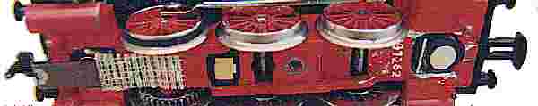
 The adjacent picture provides an impression of how the finished TELEX - coupling appears from below (here in free-hand milled voids).
For fixing, drill and tap for 2mm set-screws. The guide loops are appropriately bent and glued at front and rear underneath the chassis; one can see this on the above picture .
As one sees in the picture, the coupling is within contact range of the pick-up shoe. The chassis must therefore be insulated above both ends of the pick-up shoe.
The magnet is best fixed the with a drop of glue. The connections to the coil, and insulation from the chassis, must be executed very carefully - because any short-circuit leads to the destruction of the magnet control electronics and/or the relevant decoder-output switches.
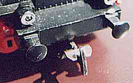 The adjacent picture shows how the custom made mechanism can look on such a 'candidate'. The original coupling hook remains. The anchor (un-coupling lever) is formed from a piece of steel sheet (I have used metal from an old transformator). At the front edge an indent is cut for the coupling hook. Where it is bent a slot is sawn, through which the shaft of the coupling hook is eventually placed, by manipulating it over the coupling hook . Another variation can be created, by modifying a simple loop coupling from e.g. a ROCO truck. These are composed of two parallel running struts with an opening in the middle, through which a relevant narrowed anchor can be brought.
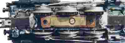
 The anchor is flexibly fastened to the chassis above the pick-up shoe . On the adjacent picture the inserted magnet can be seen on the right, and, on the left, the flexibly fastened anchor; for this I have used a piece of book-binding linen. It is flexible and at the same time durable.
As well as this one will notice on the right the above mentioned modified loop-coupling; one can clearly identify the opening, through which a suitably made anchor is taken.
This translation was made by Paul Kalbskopf from GB. Many thanks to him for this grateful work. Some mistakes you probably find are my work as result of trying to correct some misunderstandings.
